Low-Cost Stereoscopic Fundus Camera
Designing and building a low-cost device to take stereoscopic fundus images of a human retina.
EXPLORE THE PROJECT
Develop a low-cost stereoscopic fundus camera that can be mounted to a standard slit lamp
Calculate and design the optical setup using a volk digital clear field indirect BIO lens
Create a device using off the shelf parts and 3D models
Use python to develop a GUI interface on Raspberry Pi to control image acquisition
PROJECT GOALS
HOW IT WORKS
This is a handheld, battery operated, ultrasound rotation point of care (POC) device that standardizes the way ophthalmic ultrasound images are taken. This device mechanically rotates a handheld Butterfly iQ ultrasound probe across the human probe to acquire images of the globe. Videos and images of the globe are converted into image slices that are then stitched together in a computer to render a 3D image of the anatomical structures of the eye, which can be used for evaluation and diagnosis. This device can be used at the bedside, in the OR, or in any low-resource setting.
MK1
The MK1 device uses 3D printed parts, binocular indirect ophthalmoscope, two monoculars, a 20D lens, two 5MP cameras, and a raspberry pi to both control the cameras using a graphical user interface and process the images. The 3D printed parts correctly position the 20D lens from the 5MP cameras imaging plane and optical axis. Cameras are optically aligned using small 3D printed frames that can be micro-adjusted in X, Y, Z, and a vertical rotational axis. Python was used to create a graphical user interface on a Raspberry Pi to control image and video acquisition.
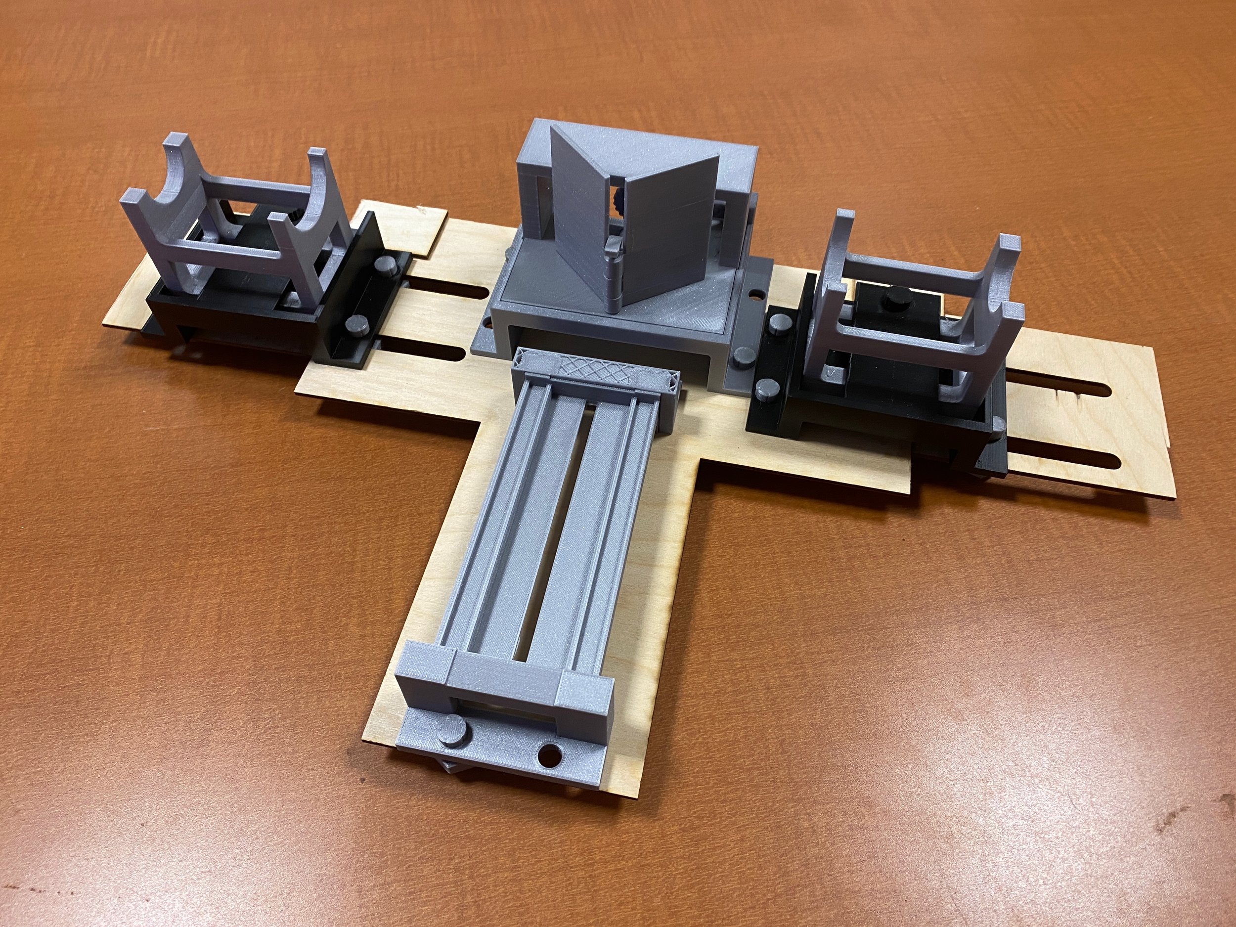
Pictures below demonstrate the experimental measurements and optical orientation that aligned with the theoretical calculations. Additionally, below demonstrates the positioning jig that aligns a monocular with the 5MP Raspberry Pi cameras. The image demonstrates the gear mechanisms that allows for micro-adjustments of the 5MP cameras into the optical axis by moving it forward/backward, left/right, up/down, and on a z-axis rotation (A-C).
The second iteration of this device was redesigned from the ground up to use the higher resolution 12MP Raspberry Pi HQ cameras with 7.9mm Sony IMX477R sensors and C-mount lenses. A custom mirror mechanism was designed allow for angular movement
MK2

My mentees Ryan and I collaboratively designed and modeled the parts in Fusion 360 and printed the parts on a Prusa MKS3+. Another mentee, Micahael, helped program the Raspberry Pi GUI to take videos and photos of the retina. The final prototypes were built using the 3D printed parts, wooden components, cameras, and the Raspberry Pi computer.
HOW ITS BUILT
MK1
MK2
The image shows a Graphical User Interface (GUI) on the raspberry pi to control the 5MP cameras and process the images. The custom GUI was created using the Python programming. Right: Stereoscopic images of the same RE fundus using the described device.
RESULTS
GUI & Stereoscopic Fundus Images
Stereoscopic images taken with 2x 5MP cameras from a raspberry pi.
Goals for the next steps
FUTURE GOALS
1. Incorporate new illumination and camera into total design of MK2
We developed an easily manufacturable, economic stereoscopic camera system to capture clear images of the fundus. Coupled with its comparatively low price point, our Raspberry Pi stereographic fundus camera system can be utilized for sustainable ocular imaging in developing countries.
2. Integrate data acquisition of Rasberry Pi into clinical workflow
PRESENTING THE WORK
We are extremely grateful to the Association for Research in Vision and Ophthalmology (ARVO) for awarding my mentee, Michael Li, and me a travel grant to present this work at the 2021 Virtual ARVO conference.