Human Interface of a Two-Photon Ophthalmoscopy System
Designing and building a method to position a human pupil into the optical axis of a two-photon ophthalmoscopy system
EXPLORE THE PROJECT
Develop a human interface device to remotely move a human head in 3-axes (up-down/Z-axis, left-right/X-axis, and forward-backward/Y-axis) to align a pupil into the optical axis of a two photon excitation fluorescence (TPEF).
Develop a pupil camera for the user to validate position of the eye in line with the optical axis that fits the size, orientation, and space constraints of the TPEF ocular
Develop a system that can be utilized in almost complete darkness (the TPEF system needs to operate in darkness to reduce photons from the background and improve the SNR).
PROJECT GOALS
HOW IT WORKS
To read more about the TPEF device and the fundamental principles the Wojtkowski and Palczewski groups have published their results here.
Motorized Chin Rest System
The motorized chin rest utilizes a combination of off-the-shelf and 3D printed parts to move a human subject's head and chin in 6 directions - up, down, left, right, forward, and backward - to correctly position the eye in line with the TPEF optical axis. The system uses an Arduino microcontroller with microstepper drivers inside a 3D printed control box. The control box uses directional arrow push buttons so that the user can operate can use tactile feedback to use the device in complete darkness.
Final Chin Rest Design
Below is the finalized version of the electronically controlled motorized chin rest to help position human subject eyes in the laser optical axis of the TPEF device. Able to move chin/head/eye in 6 directions: forward/backward, up/down, left and right.
Create a robust, stable motorized X-axis mechanism since the entire motorized chin rest is built on top. In the first iteration of the horizontal axis there were no robust mechanisms to prevent rocking of the chin rest once it was mounted with a human head in place.
Create a motorized mechanism to turn the rotational screw in Thorlabs translational stage while also being able to move with the entire stepper-translational stage-gear mechanism along with the horizontal slide table. A 3D printed adapter was used to help fit a nut inside the T-slot extrusion to secure the Y-axis translational stage to the horizontal/X-axis translational stage.
Develop a system to ensure contact between the stepper motor and the lab jack axel at whatever height the lab jack stand was positioned. When the stepper motor turns the lab jack axels to raise the platform, the entire lab jack axels linearly translate outwards, which also moves the stepper motor outward. When the axel is rotated to lower the platform the axel and stepper motor moves inward. Because we wanted to develop a system that did not rely on adhesives/epoxy (if possible) to maintain contact between the stepper motor and lab jack axel, tensions springs were used to apply a compressive force and maintain the interface.
Design Challenges
Electronic Control Box
The electronic control box is designed to be used in a low latency application that does not require a screen, an operating system, and the power supply can be cut from the system without harming the electronic control board
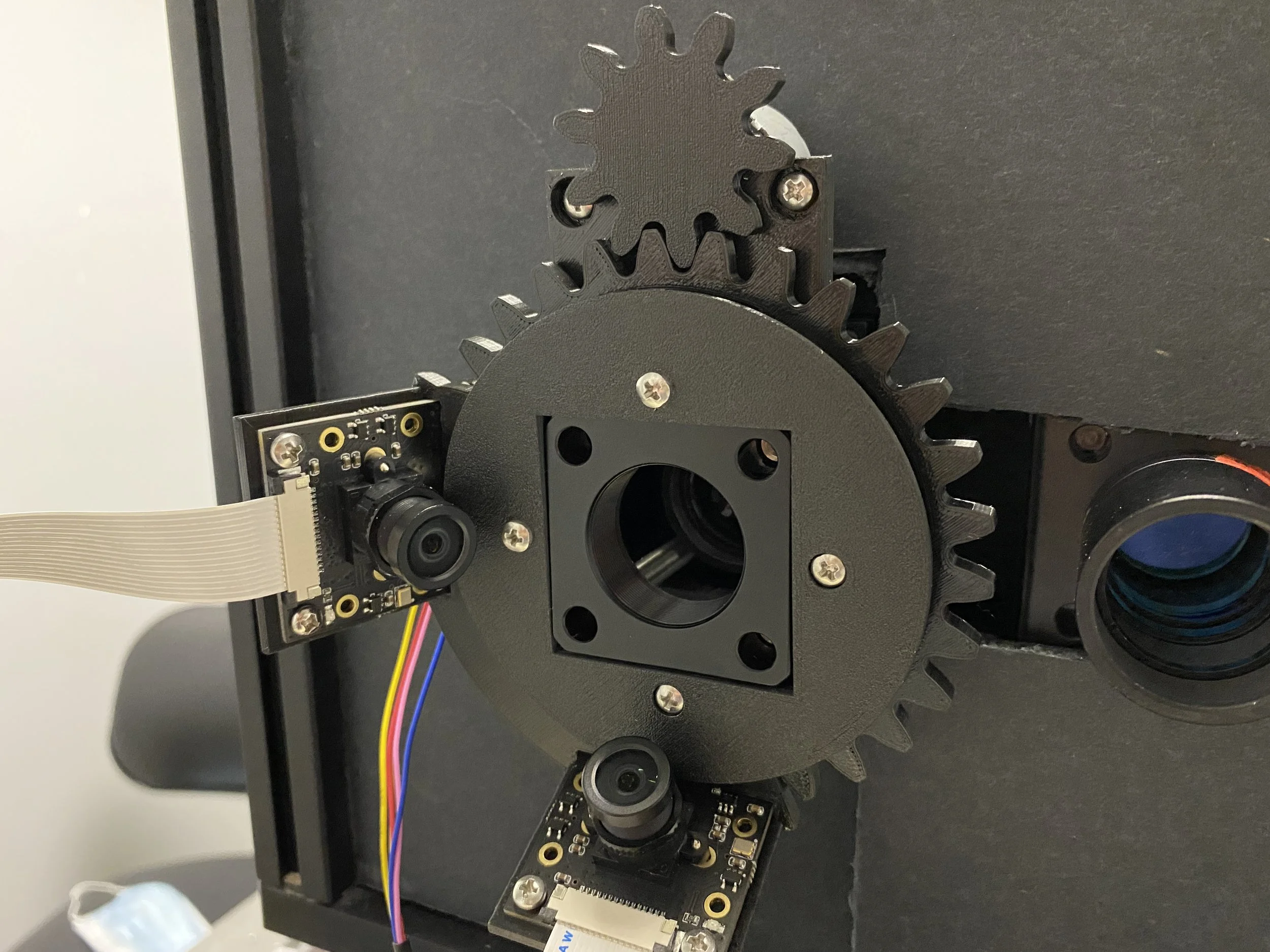
The pupil camera was designed so that it can be used for both the right and left eye. After testing different camera positions angled at the pupil we found that the superior and nasal positions (with respect to the pupil) were less desirable positions because the frontal bone in certain ethnicities (typically caucasian) were more prone to blocking the visual axis of a camera positioned above the orbit angled down. Similarly for a camera in the nasal position pointed towards the pupil, the nose bridge of certain ethnicities (typically caucasian) are also more prone to blocking the camera optical axis. Therefore I designed the cameras holders to point the optical axes towards the pupil be but positioned laterally and inferiorly.
Infrared Pupil Camera
Goals for the next steps:
FUTURE GOALS
There are current space limitations between the human TPEF device and the human subject when the ”Y-axis” mechanism is currently setup to face the patient. The motor system moving the chin rest forward and backward needs to be redesigned with a shorter track.
Y-axis Mechanism Orientation
The next step is to connect the IR camera motor mount to the electronic control box and the cameras to the computer to view the position of the pupil in the dark.